PID Control for Line Following Robot
A Lego EV3 robot races down a line of black tape, smoothly navigating sharp turns, and skidding to a stop in front of a box blocking the path. This was the objective of my mechatronics course’s final project. I worked with two classmates to create sensor circuits, implement PID control, and build a robot with a picture of that racing robot in mind.
PID Based Line Following
Following a black line on a white background seems like a simple enough task, but achieving fast, smooth tracking while handling sharp turns requires a non-trivial algorithm. Fortunately, PID control is straight forward to implement and provides great results if properly tuned.
The idea behind PID control is simple: the difference between what you want, the set-point (SP), and what you observe, the process value (PV), determines how you react. The reaction can be tuned with the three constants: \( K_p \) , \( K_i \) , and \( K_d \) .
\[e(t) = SP - PV\] \[u(t) = K_p e(t) + K_i \int_{0}^{t} e(\tau) d\tau + K_d \frac{de(t)}{dt} \]The difficulty with PID control comes in tuning the constants. Manual tuning and using a PID tuning technique called the Ziegler-Nichols method both proved unsuccessful in our attempts. However, we were able to get a successful combination of constants by increasing \( K_p \) until the robot started to heavily oscillate, then increasing \( K_d \) to dampen the oscillations, and repeating until the robot could handle sharp turns with smooth execution.
It is important to know that the derivative term can amplify the effects of noise. Since we had a good amount of noise in our measurements and the noise frequency was much higher than the dynamics of our application, low pass filtering our measurements was crucial. Using a moving average filter removed unwanted noise while maintaining the integrity of the signal. This allowed the derivative term to improve our robot performance instead of throwing our robot off course.
Robot Design
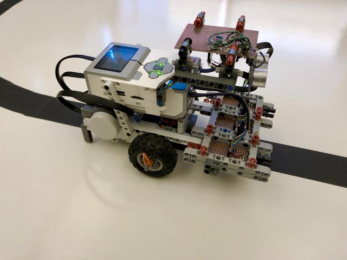
The best PID control cannot compensate for a poor system. This is why building an agile robot with robust sensing was so important. To create a responsive robot, we placed the drive motors in the front of the vehicle near the sensors. This allowed sensing and control to be more tightly coupled. Also, a low friction leg was put in the back so that the robot could turn freely.
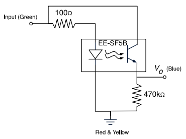
For the robot to detect the full range of possible headings (from “far left of the line” to “far right of the line”), three reflective light sensors were positioned in front of the robot across the width of the line. Placing the sensors very close to the ground resulted in better sensitivity but the area measured by the sensor was too small for our application. Since it was necessary for our robot to see as much of the line as possible to detect its heading, a sensor height of 2.8 cm was selected. This provided the best balance of coverage area and sensitivity. In order to provide the robot the ability to handle sharp curves, the sensors were placed as close as possible to the axis of rotation. The reflective light sensor used was the EE-SF5B. Below is the schematic showing how the sensor was interfaced with the EV3 using a 6-pin connector cable.
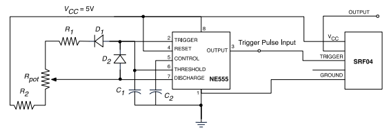
To see any objects blocking the path, an ultrasonic sensor was mounted above the color sensors pointing toward the forward direction of travel. The ultrasonic sensor used was the SRF04. To have the sensor sample continuously, the SRF04’s trigger was connected to a NE555 timer IC. The capacitors and resistors used in the NE555 circuit determine the frequency and pulse width of the output. Resistor and capacitor values were selected to achieve a 30ms period with a 1ms pulse width. This was necessary for the SRFO4 to trigger properly. The PWM output from the SRF04 was put through an RC low pass filter so that the EV3 could sample it. The ultrasonic circuit is shown below.
With the robot constructed, sensors mounted, and PID control completed, I was proud to show off our robot during the project demonstration. Our robot raced around the track, smoothly tracking each turn, and our goal had come to light.